How Can We Help?
LIDAR Implementation
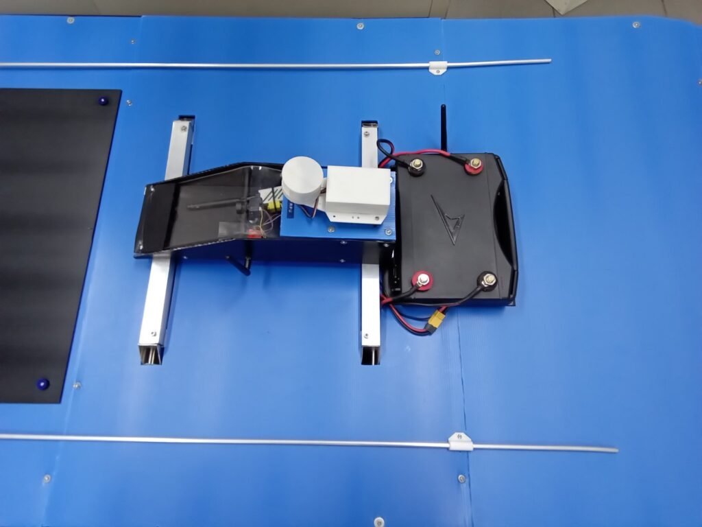
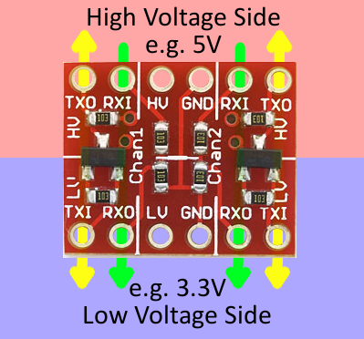
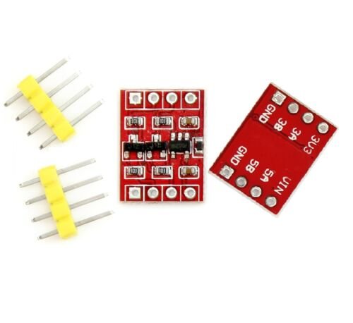
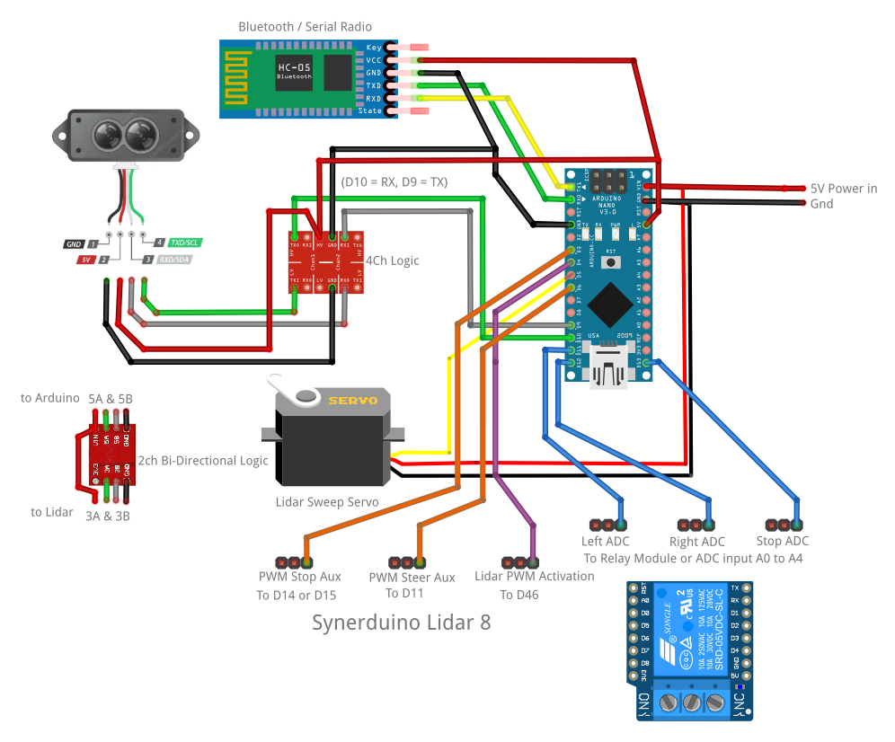
Collision avoidance with Lidar implementation with the TFMini Plus or TFMini-S as with sensors use for collision detection Lidars are more precise in measurement and less on false positives unlike the Ultrasonics hence is ideal for longer range detection with this one upto 10m . also this LIDAR sensor uses 3V logic and require Logic converters to operate there are 2Ch and 4Ch Bidirectional Option . in this sample we shown using the 4Ch. but if available go with the 2ch option.

Note: there are instructables online showing the LIDAR Directly hookup to the Arduino (Please use the Logic converter) plugging it directly would damage the sensor in the long run.

Read Application
available in Linux and Windows 32 and 64
Application 57600 – Baud 57600 Forward Servo
Application 57600 – Baud 57600 ReverseServo
Application 115200 – Baud 115200 Forward Servo
Application 115200 – Baud 115200 Reverse Servo
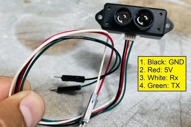
RX-10 ,TX-9 use Logic converter // TX-Green-3A RX-White-3B// 5A-D9 5B-D10
Lidar PWM Activation D4 is your Lidar switch Aux input 1000ms RC PWM is Off and 2000mm RC PWM is On, LIDAR switch this can be paired with your Aux switch lets say missions so the LIDAR is only Active when Mission is Active.
PWM Stop Aux D3 Trigger detection this can be connected to one of the free aux channels ie (Mainly puts the vehicle on Position hold or do other action when obstacle is detected at the given range )
PWM Steer Aux D6 or D7 Trigger detection this can be utilize as steering as it can be set points towards or away from the direction of Lidar
ADC D11 D12 D13 this serves as an ADC input and can be utilize on the Logic programing of Synerduino STM or blink some LEDs
Read Arduino Sketch
10 Meter range TFMini Plus or TFMini-S (2023 update distance of Lidar to 10 meters Note: sensitivity or acurracy may Vari )
Inorder for this to work Bluetooth radio must be set to a on Communication serial on any device to baud 57600
Lidar_Forward and Lidar_Reverse are servo reverse option
in the application folder look for the Data file>Data Folder>
COM31 //Serial COM Port your bluetooth telemetry is on (change this to the comport your Raday Bluetooth/Radio is on)
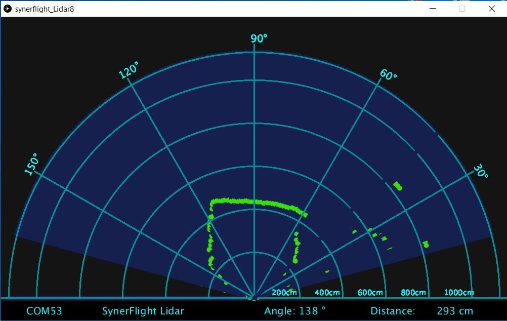
SynerFlight Radar //Title of the Radar
Arduino Sketch> TF-mini-synerduino3.ino
int inputdistance = 200; // set Distance to trigger the PWM Aux Switch in cm (change this to adjust trigger distance)Stop
int inputdistance1 = 250; // set Distance to trigger the PWM Aux Switch in cm (change this to adjust trigger distance)Steer
SoftwareSerial Serial1(10, 9); //define software serial port name as Serial1 and define pin2 as RX & pin3 as TX
RX-10 ,TX-9 use Logic converter // TX-Green-3A RX-White-3B// 5A-D9 5B-D10
myServo.attach(5); // Defines on which pin is the Radar servo motor attached this is where the Lidar is mounted to
Aux output to be connected to the Aux input of the Controller
myServo.attach(5); // Defines on which pin is the servo motor attached // Lidar Servo
myServoA.attach(3); // (Stop) Defines on which pin is the servo motor attached // PWM Output to flight controller
myServoB.attach(6); // (Steering) Defines on which pin is the servo motor attached
myServoC.attach(7); // Defines on which pin is the servo motor attached
digitalWrite(4 , __ardublockDigitalRead( ardublockUltrasonicSensorCodeAutoGeneratedReturnCM( 4 , 4 ))); // pwm input condition to activate the Lidar respond function
Synerduino Application
Note: the application has its corresponding baud as application name and in the application folder contains a data folder > data.txt COM20 change this to suit your comport your devices is assign to
Firmware hex file and hex uploader
supports 328P boards Nano and Promini
Synerduino Lidar Sketch for Processing .org and Arduino
Ardublock file for Lidar