How Can We Help?
MTF-01 Optical FLOW and LIDAR
suitable for indoor operation without GPS
Setup your MFT-01
Application
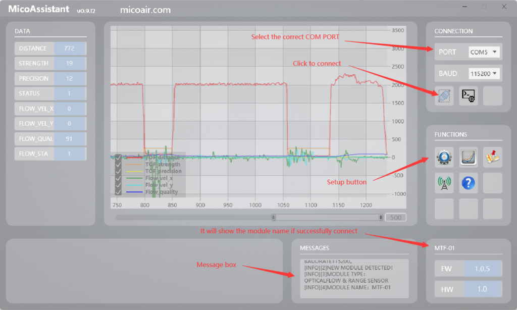
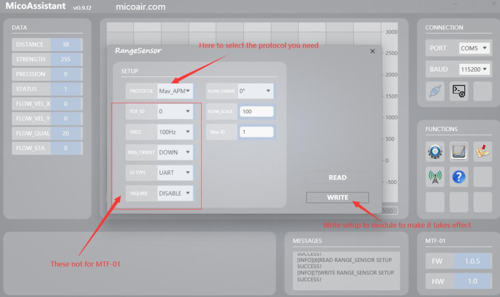
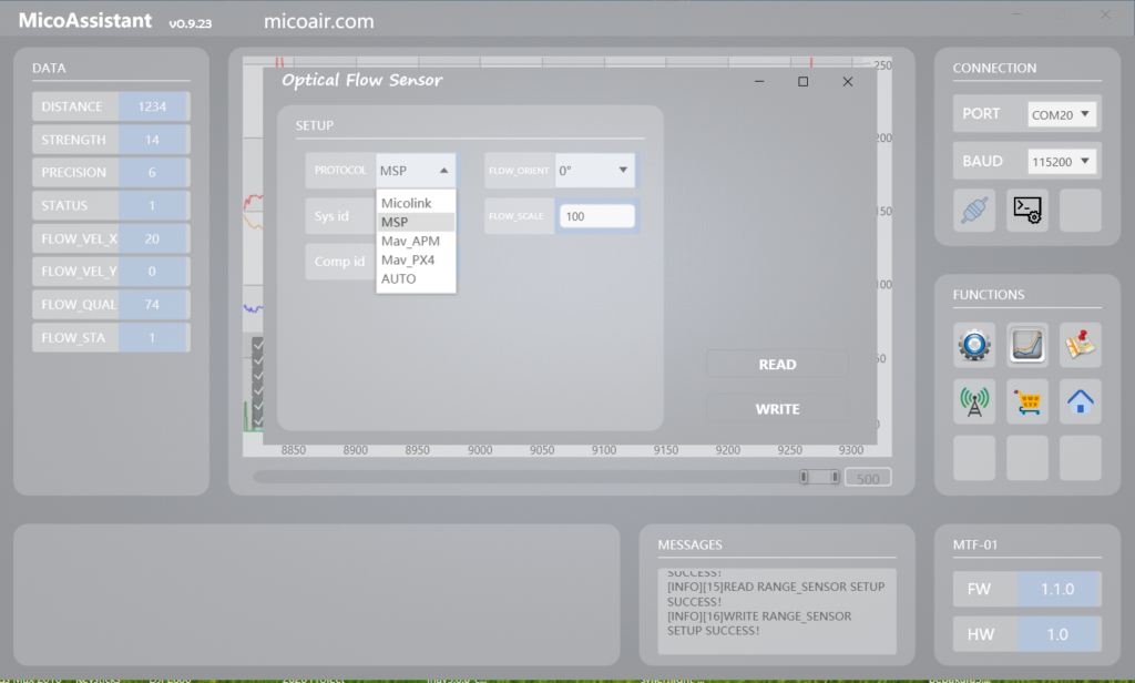
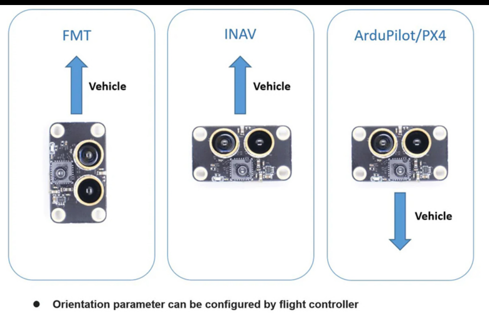
Select your protocol
MSP for INAV
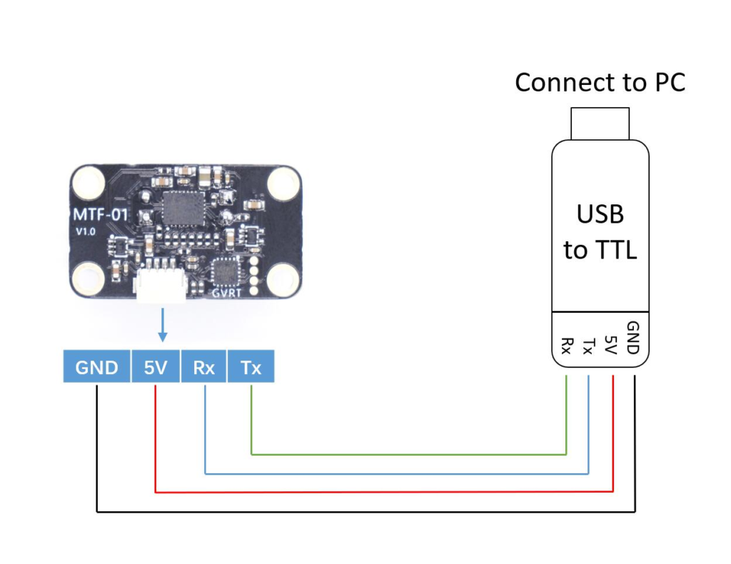
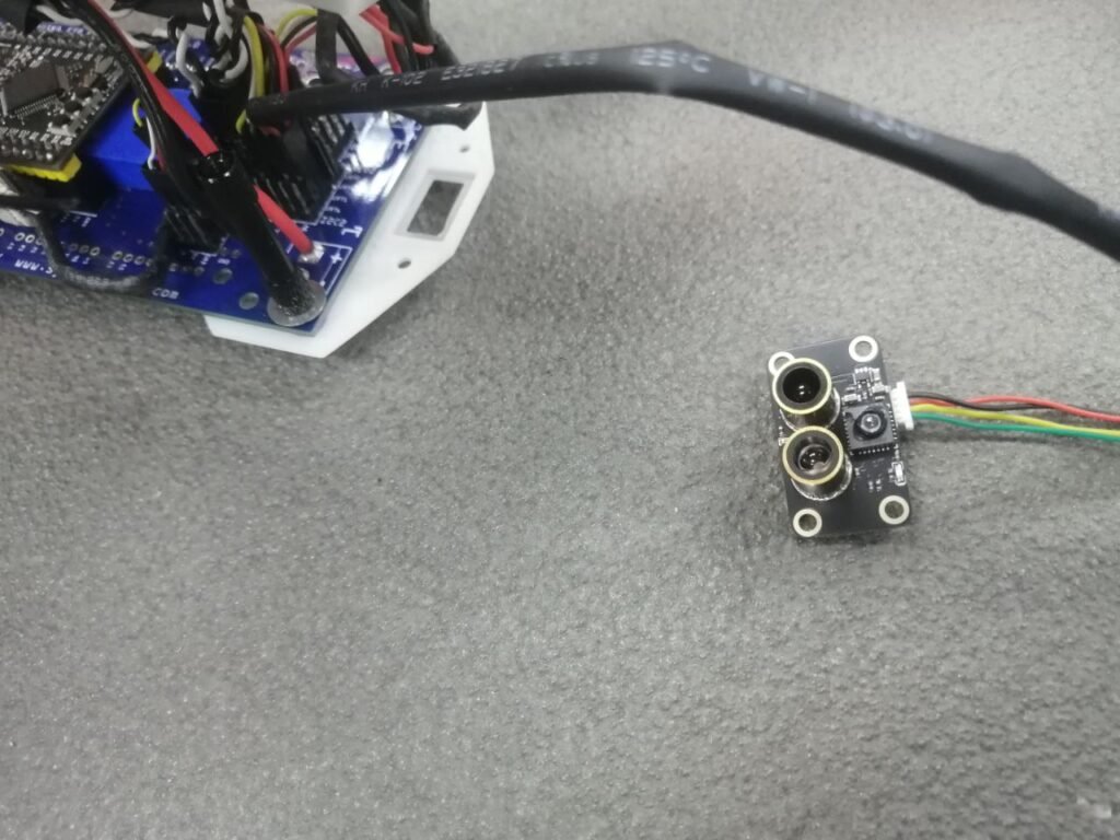
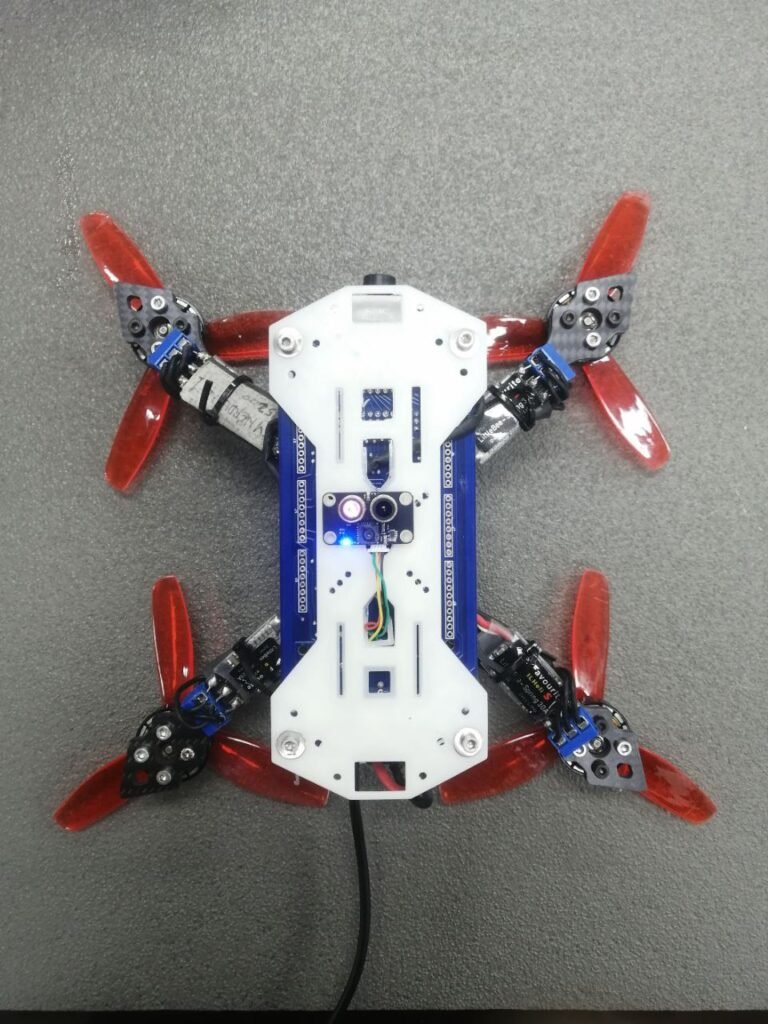
Hardware installation to Synerduino
INAV setup

here we place is on UART 6 as this is one of the ports available at MSP 115200 baud
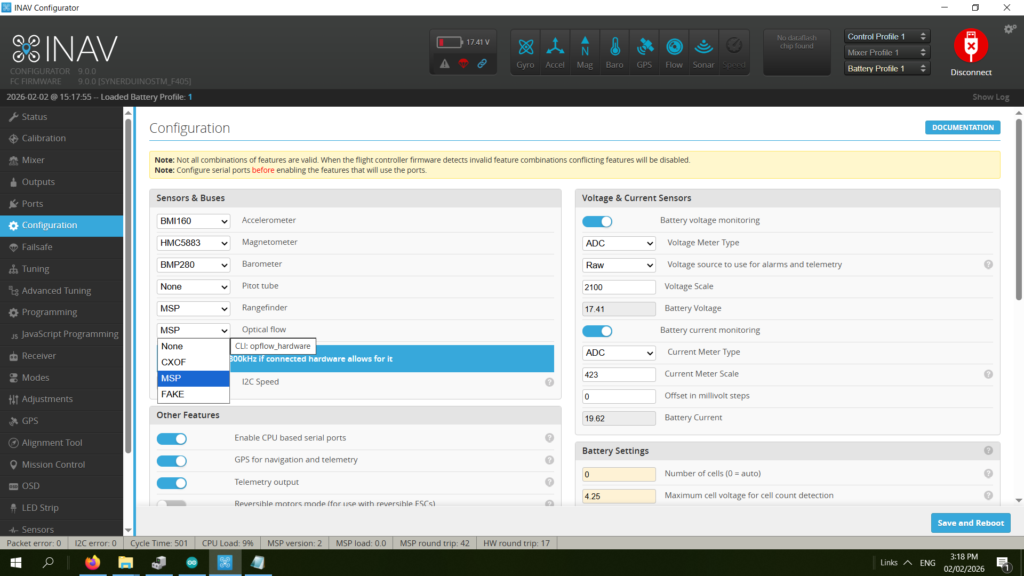
Set Optical flow and Rangefinder to MSP
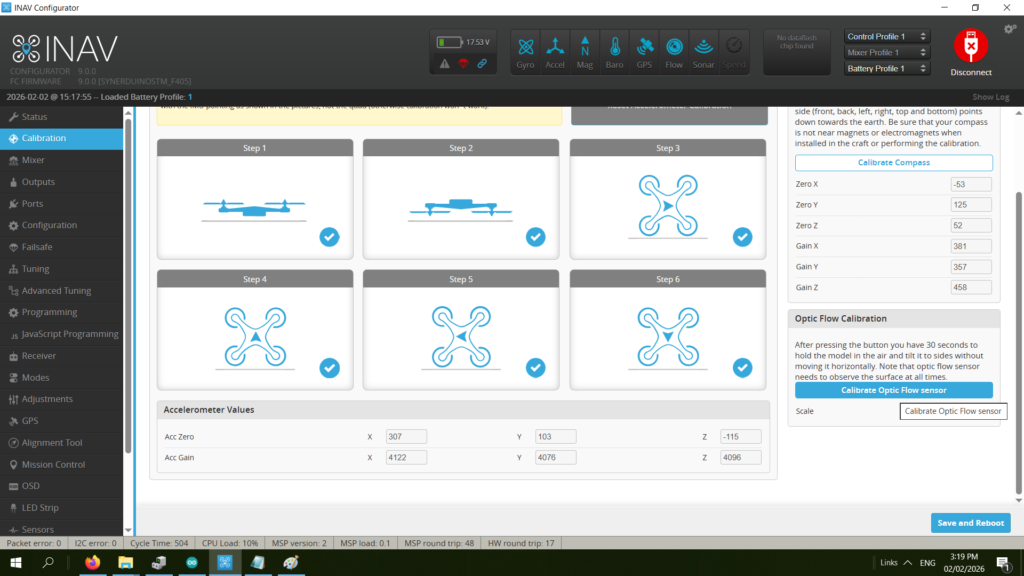
Calibration if the optical flow
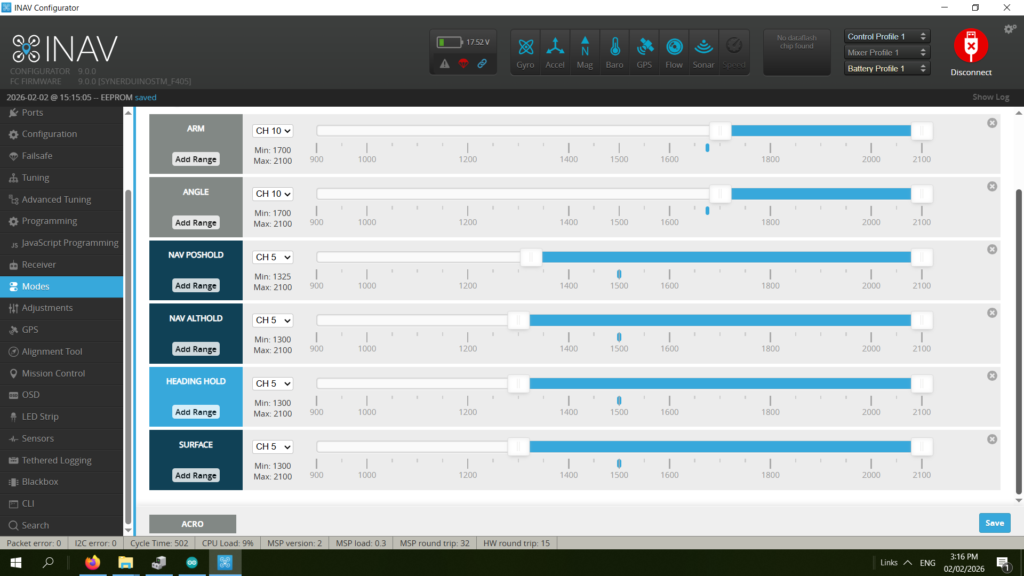
Set modes to activate sensor
- ANGLE
- NAV Poshold
- NAV Althold
- Heading Hold
- Surface
INAV
set nav_mc_vel_z_p = 100
set nav_mc_vel_z_i = 250
set nav_mc_vel_z_d = 15
set nav_mc_pos_xy_p = 60
set nav_mc_vel_xy_p = 50
set nav_mc_vel_xy_i = 40
set nav_mc_vel_xy_d = 50
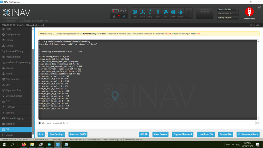
CLI Command in the video:
set debug_mode= FLOW_RAW
set inav_allow_dead_reckoning=ON
set nav_max_terrain_follow_alt = 200
set inav_max_surface_altitude = 200
set nav_mc_vel_z_p = 150
set nav_mc_vel_z_i = 250
set nav_mc_vel_z_d = 25
set nav_mc_pos_xy_p = 80
set nav_mc_vel_xy_p = 50
set nav_mc_vel_xy_i = 40
set nav_mc_vel_xy_d = 60
save
Sensor Tab
In the Sensors tab, gently tilt the quad side to side and front to back.
The waveform of Debug 0 should look similar to Debug 2,
while Debug 1 should look similar to Debug 3.
Sensors Tab
Debug 0/1 represents the accelerometer readings,
while 2/3 are from the optical flow sensor.
This test verifies the orientation of the optical flow sensor.
The amplitude might not be the same,
but if they move in the opposite direction,
you might need to change the configuration in MicroAssistant
(or set align_opflow=cw180 in CLI).
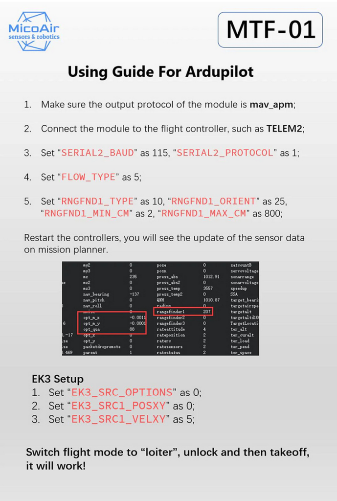
Ardupilot