
How Can We Help?
Motor Driver to read RC PWM
For Some who use Motor Driver H-bridge boards
Using L293D or L298N would require an Arduino its self as an Bi-direction ESC substitute for surface vehicles which serves as an pwm converter from the synerduino shield
L293D is a quadruple motor driver that uses a half-H driver while L298N is a dual full-H driver, i.e, in L293D all four input-output lines are independent while in L298N, a half-H driver cannot be used independently, only a full H driver has to be used. in a typical PWM servo signal the 1000ms to 2000ms where the 1500ms is center or neutral position. Note that RC PWM inputs are on A0 & A1 pins on the Arduino
Ardublock For block code Programing , files in (.abp)
Download as Link Ardublock.jar
L298N Motor Driver
- OPERATING SUPPLY VOLTAGE UP TO 46 V.
- TOTAL DC CURRENT UP TO 4 A.
- LOW SATURATION VOLTAGE.
- OVERTEMPERATURE PROTECTION.
- LOGICAL ”0” INPUT VOLTAGE UP TO 1.5 V

the L298N is typical 2 H-bridge set one for each motor with 4 inputs two of which is represent by two motors
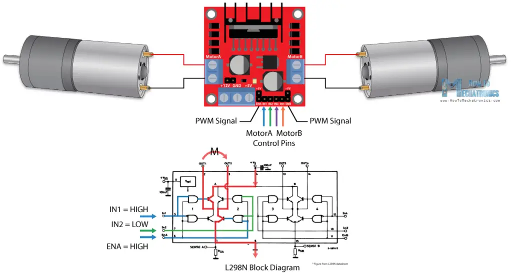
- A0 1000ms-1400ms as Reverse (Motor Driver)A out 1 & 2 input 1 (low) Input2 (high) (Arduino Pins D2 & D3)
- A0 1500ms as Stop or Release (Motor Driver) A out 1 & 2 (low) Input2 (low) (Arduino Pins D2 & D3)
- A0 1600ms -2000ms as Forward (Motor Driver) A out 1 & 2 input 1 (high) Input2 (low) (Arduino Pins D2 & D3)
- A1 1000ms-1400ms as Reverse (Motor Driver) B out 3 & 4 input 3 (low) Input 4 (high) (Arduino Pins D4 & D5)
- A1 1500ms as Stop or Release (Motor Driver) B out 3 & 4 input 3 (low) Input4 (low) (Arduino Pins D4 & D5)
- A1 1600ms -2000ms as Forward (Motor Driver) B out 3 & 4 input 3 (high) Input 4 (low) (Arduino Pins D4 & D5)
L293D Motor Driver
- 600mA OUTPUT CURRENT CAPABILITYPER CHANNEL
- 1.2A PEAK OUTPUT CURRENT (non repeti-tive) PER CHANNEL
- ENABLE FACILITY
- OVERTEMPERATURE PROTECTION
- LOGICAL ”0” INPUT VOLTAGE UP TO 1.5 V
- (HIGH NOISE IMMUNITY)INTERNAL CLAMP DIODES
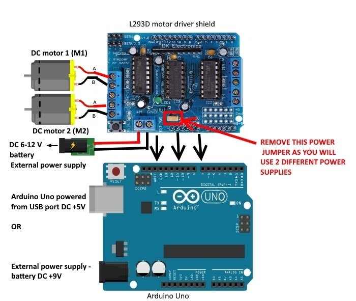
which also introduce the Adafruit Motor driver Shield L293D which uses a decoder to process the signal . Before you can use the Motor shield, you must install the AF_Motor Arduino library – this will instruct the Arduino how to talk to the Adafruit Motor shield, and it isn’t optional!


- A0 1000ms-1400ms as Reverse Motor 1
- A0 1500ms as Stop or Release Motor 1
- A0 1600ms -2000ms as Forward Motor 1
- A1 1000ms-1400ms as Reverse Motor 2
- A1 1500ms as Stop or Release Motor 2
- A1 1600ms -2000ms as Forward Motor 2
due to current limitation L293D of this Adafruit shield the maximum size motor would safely operate is below 600mA like the Type-130 , Type-140 , Type-260 at 3V-5V arduino sketch along with the ardublock file (download) has the Motor A (1) input A0 and Motor B (2) input A1 respectively . should be sufficient for differential drive surface vehicles . Further more test to be followed